GSM technology is used to communicate with mobile phones. GSM stands for Global System for Mobile communication. In arduino GSM tutorial, we will be interfacing GSM module with arduino board. GSM modem interfacing with arduino is very easy. We simply need 4 pins to connect to the arduino. These pins are GND, Vcc, RX and TX. Once we know the interfacing and programming we can make call and SMS.
There are different GSM modems like SIM900 and SIM300 available in the market with different onboard facilities like USB, rs232 and serial interface. We can also use GSM shield that is easily stacked over the arduino board. Some modems have a GPS module inbuilt to provide the longitude, latitude and other features of GPS.
Table of Contents
GSM Modem – SIM900/SIM300
What GSM modem is good SIM300 or SIM900
SIM300 is triband GSM modem and operates at 900,1800,1900MHz band.
SIM900 is quad band GSM modem and operates at 850,900,1800,1900 MHz bands. And also have GPRS functionalities useful in web enabled applications.
Select the GSM modem that supports the frequency band in your country.
You can find GSM Bands information by country.
GSM Modem Power Requirement
There is a different manufacturer of the modem. And their supply voltage and current requirement may different. So before applying the supply check the datasheet of the modem. We are using the modem with 12V and 1.5Amp current. If we provide less current like 500mA. The modem will show the supply on the board but it will not operate correctly. And never get their GSM network due to less current.
GSM Modem – Booting
Insert the SIM Card in the GSM modem. Before using GSM modem make sure it is booted completely. There is a LED on the GSM board that blinks continuously when it doesn’t find any GSM network signal. Once it detected the network its blink rate will slow down. To confirm that GSM modem is working you can make a call. And you can hear the dialling tone on your mobile.
Hardware Required
- Arduino Uno
- GSM Modem
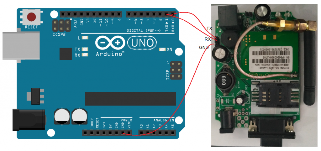
GSM Arduino Connection
GSM interfaces with the arduino using serial communication. For this interfacing, you should know what is serial communication in arduino. We are connecting the modem as we have learned from the serial tutorial.
GSM AT Commands
AT commands are the instructions used to command the modem. AT is the abbreviation of Attention. All commands start with “AT” or “at”. That’s why it is called “AT” command. AT is the prefix in each command to inform the modem about the start of the command.
Arduino GSM Code for CALL
/* Arduino GSM Call */
void setup()
{
  Serial.begin(9600);  //Baud rate of the GSM Module
  delay(1000);
  Serial.print("ATD +91xxxxxxxxxx;\r"); //Phone number you want to call
}
void loop()
{
}
Arduino GSM Code for SMS
- AT+CMGF=1 Set modem in text mode
- AT+CMGS=”+91xxxxxxxxxx” SMS to this mobile number
- Message Text
- Message closing character Ctrl+Z(terminate and send)
/* Arduino GSM SMS */
void setup()
{
  Serial.begin(9600);  //Baud rate of the GSM/GPRS Module
  delay(1000);
  Serial.print("AT+CMGF=1\r");
  delay(1000);
  Serial.print("AT+CMGS=\"+91xxxxxxxxxx\"\r");    //Phone number you want to send the sms
  delay(1000);
  Serial.print("Hello Maxphi\r");   //Text message you want to send
  delay(1000);
  Serial.write(0x1A); //sends ctrl+z end of message
  delay(1000);
}
void loop()
{
}