An Arduino home automation project can be made using different wireless technology like Bluetooth, WiFi, Android Mobile or using IR remote control. We use the relay in arduino home automation project to control the home appliances. We use IR remote control to control the home appliances remotely.
But how to make arduino home automation project using a relay, remote and LCD modules and how to control them. The main part of the arduino home automation project is to control arduino with ir remote control. For that, we need to understand How to Decode IR Remote Control Signals using arduino IR remote library.
By this tutorial, we can decode any ir remote control or tv remote control signals. So the same arduino home automation project can be made using the tv remote control.
We are controlling the three home appliances using the IR remote control. This can be a Fan, Bulb, and AC. For controlling these home appliances we need three relays.
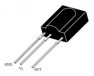
To get the remote control signals, we use the TSOP1738 ir receiver. This TSOP1738 ir receiver accepts only 38KHz ir signals coming from the IR remote control or tv remote control. The remote control button has some unique value or data to each button. The button value is sent in the form of ir signal at some frequency like 38KHz. The remote control frequency may depend on the remote control model. This transmission from remote has some form of modulation so the transmission range of remote control signal is quite far.
The main heart of arduino home automation project using IR remote control is understanding of decoding remote control signals.
Available TSOP with Different Carrier Frequencies
| TSOP | Frequency |
| TSOP1730 | 30KHz |
| TSOP1733 | 33KHz |
| TSOP1736 | 36KHz |
| TSOP1737 | 36.7 |
| TSOP1738 | 38KHz |
| TSOP1740 | 40KHz |
| TSOP1756 | 56KHz |
Table of Contents
TSOP1738 Pinout
Arduino Home Automation Project Remote Control Signal Decoding
We use IR Remote Library to decode the remote signal. While decoding the signal make sure TSOP1738 output is connected to PWM of the arduino board. Note down the decoded remote control signal of the button you want to control home appliances using remote control.
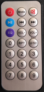
Remote Control used in Arduino Home Automation Project
We are using this simple remote control for arduino home automation project. This is easily available online and at a local store. This remote control sends the signal at 38KHz.
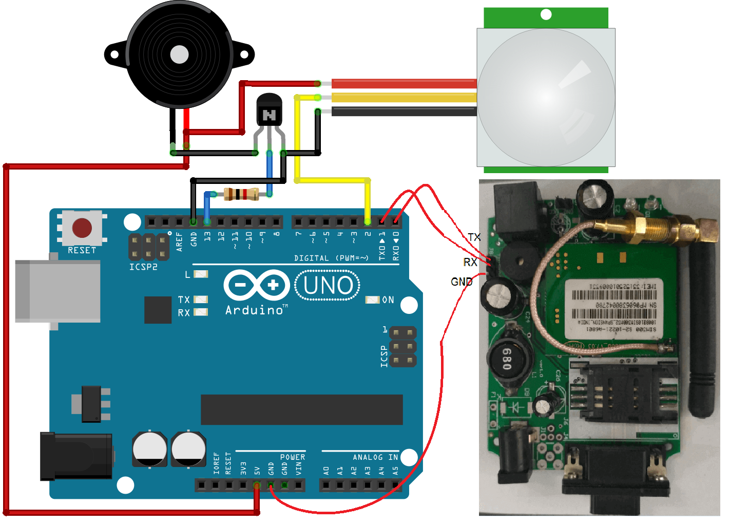
Arduino Home Automation Project Connections
LCD Connections with Arduino
RS – Digital Pin 3
RW – GND
E – Digital Pin 2
D4 – Digital Pin 4
D5 – Digital Pin 5
D6 – Digital Pin 6
D7 – Digital Pin 7
Arduino Connection with Relay
A0 – Relay1(FAN)
A1 – Relay2(BULB)
A2 – Relay3(AC)
TSOP Connection with Arduino
Out – Digital Pin 9(PWM)
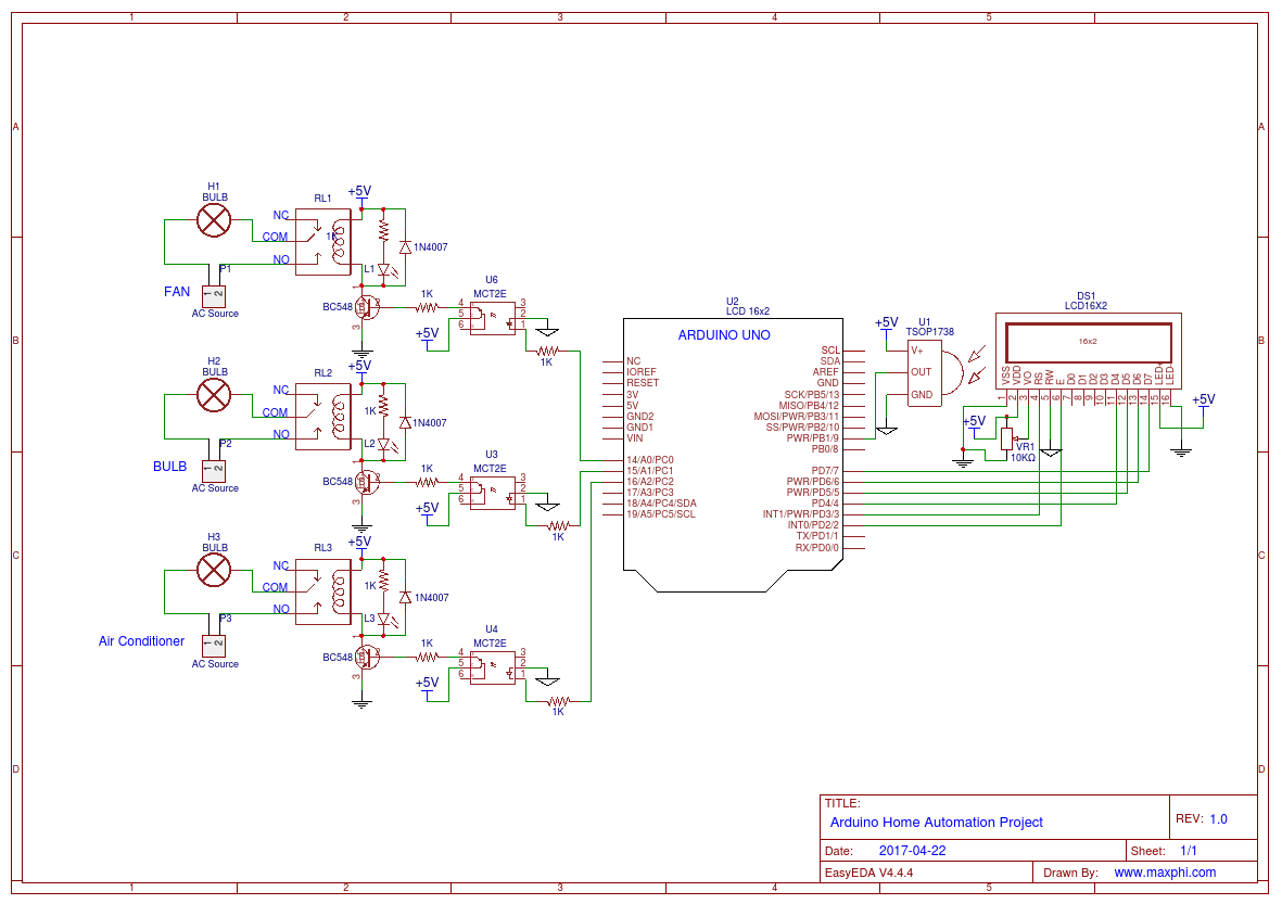
Arduino Home Automation Project using IR Remote Control Relay Circuit
This is home automation using arduino circuit designed using the https://easyeda.com. The arduino home automation circuit is available in public view.

The IR receiver is connected to digital pin 9. This pin should be a PWM pin. The relay is connected to analog pin A0, A1, and A2. We have used the MCT2E optocoupler to isolate the signal from the arduino and load connected to the relay. This optocoupler also provides the isolation from the noise and short circuit at relay side.
At the output side of the MCT2E, a BC548 NPN transistor is connected to trigger the relay. Here transistor simply acting as a switch for the relay.
We have used button 1, button 2 and button 3 of an ir remote control for controlling FAN, BULB and AC respectively. The hex code value of the buttons after decoding.
| Button | Hex Value |
| 0 | 0x1FEE01F |
| 1 | 0x1FE50AF |
| 2 | 0x1FED827 |
| 3 | 0x1FEF807 |
| 4 | 0x1FE30CF |
| 5 | 0x1FEB04F |
| 6 | 0x1FE708F |
| 7 | 0x1FE00FF |
| 8 | 0x1FEF00F |
| 9 | 0x1FE9867 |
Arduino IR Home Automation Code
This sketch read and decode the ir signal using the IRrecvDemo.ino available at the IR remote library. After that, we have written the code that receives the ir signal and matches using the switch statement.
If button 2 is pressed then
case 0x1FE50AF: relay1=~relay1;// Button 1
break;
The following part will execute and the variable relay2 will change from initial 0 to 1. Then we check using the if statement whether a relay2 variable is set or reset. According to that, we signal the relay to trigger ON or OFF.
Arduino-Home-Automation-Project-using-IR-Remote-Control-and-Relay.ino
#include <IRremote.h>
#include "pins_arduino.h"
#include <LiquidCrystal.h>
int RECV_PIN = 9;//Pin should be PWM

IRrecv irrecv(RECV_PIN);
// initialize the library with the numbers of the interface pins
LiquidCrystal lcd(3, 2, 4, 5, 6, 7);
decode_results results;
int relay1=0,relay2=0,relay3=0;
void setup()
{
  irrecv.enableIRIn(); // Start the receiver
  pinMode(A0,OUTPUT);//Relay1
  pinMode(A1,OUTPUT);//Relay2
  pinMode(A2,OUTPUT);//Relay3
   lcd.begin(16, 2);
}
void loop() {
  lcd.setCursor(0,0);
  lcd.print("Home Automation");
  if (irrecv.decode(&results)) {
      switch(results.value)
      {
        case 0x1FE50AF:  relay1=~relay1;// Button 1
                         break;

        case 0x1FED827:  relay2=~relay2;// Button 2
                         break;

        case 0x1FEF807:  relay3=~relay3;// Button 3
                         break;
      }
    irrecv.resume(); // Receive the next value
  }
  if(relay1)
  {
    digitalWrite(A0,HIGH);
    lcd.setCursor(0,1);
    lcd.print("R1=1");
  }
  else
  {
    digitalWrite(A0,LOW);
    lcd.setCursor(0,1);
    lcd.print("R1=0");
  }
  if(relay2)
  {
    digitalWrite(A1,HIGH);
    lcd.setCursor(5,1);
    lcd.print("R2=1");
  }
  else
  {
    digitalWrite(A1,LOW);
    lcd.setCursor(5,1);
    lcd.print("R2=0");
  }
  if(relay3)
  {
    digitalWrite(A2,HIGH);
    lcd.setCursor(10,1);
    lcd.print("R3=1");
  }
  else
  {
    digitalWrite(A2,LOW);
    lcd.setCursor(10,1);
    lcd.print("R3=0");
  }
  delay(600);
  lcd.clear();
}
References: